5 Work order
5.1 Generating a log of elements and a digital pipeline diagram
Based on the passport submitted by the Customer, structural diagrams of the pipeline and standards for pipes, connecting parts and shut-off and control valves, a log of elements is formed, including:
- element position number according to the diagram;
- standard for pipe / part / fittings;
- standard for pipe/part/fitting material;
- spatial coordinates (X, Y, Z) of the beginning of the element (center of the cross section);
- spatial coordinates (X, Y, Z) of the end of the element (center of the cross section).
In addition to those indicated in the diagrams, welded connections between elements, branches at pipeline branch points and branches at the installation sites of supports are added to the element log. Pipeline elements (measurement points) are selected at which infrasound monitoring devices should be installed during field inspection. For branched pipelines, it is recommended to install devices in the end zones (on shut-off valves) and in branching areas (tees with flanges). The choice of installation locations for devices is also limited to areas (parts) without thermal insulation and the availability of areas without restrictions on operating modes. Typical methods for temporary installation of devices are shown in Appendix 5.1.
5.2 Performing field work to inspect the pipeline
During a full-scale examination, infrasound monitoring devices (PIK) are installed at the measurement points (clause 5.1), measurements and registration of linear accelerations, as well as angular velocities in three mutually perpendicular directions are carried out. Based on the measurement results, the amplitude-frequency characteristics of the displacements and rotation angles of the pipeline points are constructed.
5.3 Calculation of the stress-strain state of the pipeline
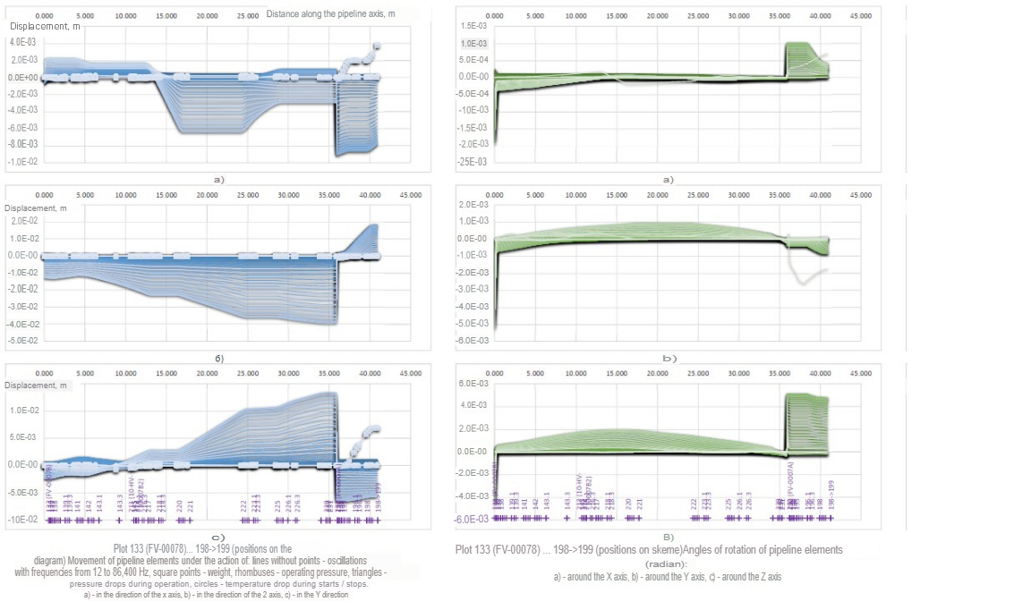
5.3.1. The pipeline section is considered as a spatial bending frame, composed of straight and curved (on bends) spans of tubular cross-section. The spans consist of pipeline elements (pipes, bends, transitions, flanges, valves, welded joints, etc.) with parameters (length, diameter, wall thickness, spatial position, material properties) corresponding to the digital diagram (clause 5.1. ), each bend is divided into 4 straight elements. The spans are connected to each other at the locations of equal tees, branches with smaller diameters, and supports. The supports are modeled by rod elements that transmit only axial forces. 5.3.2. Calculations of forced dynamic vibrations with frequencies from 1 Hz to 86400 Hz (65 frequencies) are carried out. The boundary conditions for calculations are the amplitude-frequency characteristics obtained from the data of the infrasound monitoring (clause 5.2.). The calculation results (for each pipeline element) are (Figure 5.1., lines without markers):
- movements in the direction of the X, Y, Z axes;
- rotation angles around the X, Y, Z axes;
- torsional (bending) around the X, Y, Z axes;
- forces in the direction of the X, Y, Z axes.
Figure 5.1. Sample. Distributions of displacements, rotation angles, moments and axial forces
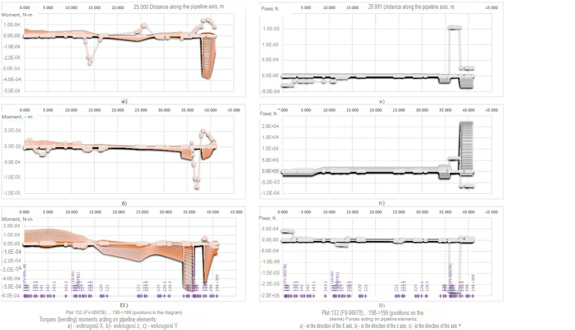
5.3.3. The deformation of the pipeline under the influence of the weight of the pipeline with the pumped product is calculated. The calculation results (for each pipeline element) are (Figure 5.1 - lines with squares):
- movements in the direction of the X, Y, Z axes;
- rotation angles around the X, Y, Z axes;
- torsional (bending) around the X, Y, Z axes;
- forces in the direction of the X, Y, Z axes.
5.3.4. A calculation is made of pipeline deformation caused by temperature differences during start-ups/shutdowns and temperature changes during operation. Linear temperature elongations of individual spans are compensated by the “own” displacements, rotations, moments and forces that arise (due to the fastening of the structure and the connection of linear spans). The calculation results (for each pipeline element) are (Figure 5.1., lines with circles):
- movements in the direction of the X, Y, Z axes;
- rotation angles around the X, Y, Z axes;
- torsional (bending) around the X, Y, Z axes;
- forces in the direction of the X, Y, Z axes.
5.3.5. A calculation is carried out of pipeline deformation caused by the difference in operating pressure during start-ups/shutdowns and pressure changes during operation. Linear extensions of individual spans are compensated by the “own” displacements, rotations, moments and forces that arise (due to the fastening of the structure and the connection of linear spans). The calculation results (for each pipeline element) are (Figure 5.1., lines with rhombuses and triangles) “own”:
- movements in the direction of the X, Y, Z axes;
- rotation angles around the X, Y, Z axes;
- torsional (bending) around the X, Y, Z axes;
- forces in the direction of the X, Y, Z axes.
5.3.6.For each element, hoop and longitudinal stresses caused by operating pressure and pressure changes during operation are calculated.
5.3.7. For each element, circumferential, longitudinal and tangential stresses caused by torsional (bending) moments and forces calculated according to p. 5.3.1.-5.3.6. Conditionally elastic equivalent stresses and corresponding elastoplastic stresses and deformations are calculated.
5.4 Strength calculation
5.4.1. In the strength calculation, the effective stresses (clause 5.3.7.) are compared with the permissible stresses according to the project or according to design standards. 5.4.2. Permissible stresses in design standards are established depending on the purpose (pumped product, temperature, flow, pressure), operating conditions of the pipeline (laying method, operating modes, external loads and influences), characteristics of the metal/material (pipes, connecting parts, fittings). In this work, we used the Building Codes and Rules Main Pipelines SNiP 2.05.06-85* (Figure 5.2.).
Figure 5.2. Sample. Effective (dark blue lines) stresses and permissible stresses according to ASME-B31.1 standards (light blue dash-dotted line)
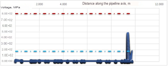 For those pipeline elements in which the effective stresses do not exceed the permissible stresses, further assessment of their condition is not required (the residual life is not limited by strength).
5.5 Calculation of residual life
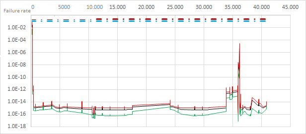
5.5.1. Based on the stress-strain state of the element (clause 5.3.7.) and the properties of the pipe metal at a temperature equal to the maximum operating temperature, the probability of failure (occurrence of a crack - destruction of the pipe wall - loss of tightness) is calculated for each type and frequency loads (clause 5.3.2.-5.3.5.) for one cycle of load change from minimum to maximum. The expected failure rate (number of failures per year) is calculated taking into account the number of cycles per year. 5.5.2. The expected total (from all loads) failure rate from all loads and the dispersion of the failure rate are calculated, taking into account the stochastic nature of the mechanical characteristics of the metal, operating modes, and the error margin of the calculation models (Figure 5.3.).
Figure 5.3. Sample. Distribution of failure rates (black line) and 90% corridor boundaries (green and red lines) along the length of the section
5.5.3. For each element, the total failure rate determines the residual life with 95% probability. By counting the residual life from the date of the diagnostic examination, we obtain the period of safe operation. National rules and regulations for calculating the residual life of pipelines have not been developed. In this work, to calculate the residual life, the calculation rules and durability criteria from the Transneft PJSC standard “RD-23.040.00-KTN-115-11” were used. Main oil pipelines and petroleum product pipelines. Determination of the strength and durability of pipes and welded joints with defects”, adapted for process pipelines examined using infrasonic testing.
5.6 Main results, conclusions, development of recommendations.
For elements with a residual life (clause 5.5.3.) 10 years or less, the reasons (types of loads) that lead to a decrease in the residual life are determined and a list of compensating measures is developed to ensure reliable and safe operation of the process pipeline.